01 / Context
Overview
The project derives a dynamic model of a five-phase induction machine using equivalent dq windings and rotating reference-frame theory. The formulation starts from phase-domain MMF relationships, introduces the five-phase transformation, and derives stator/rotor voltage and flux-linkage equations suitable for numerical simulation.
The resulting MATLAB/Simulink model was intended as a general research tool for generating operating data and injecting electrical faults. Related later projects cover multiphase control and fault diagnosis.
My work
- Derived five-phase abcde-to-dqxy0 transformations and inverse transformations.
- Derived stator/rotor voltage, flux-linkage, speed, and electromechanical relationships.
- Implemented the model in Simulink for later controller and fault studies.
02 / Approach
Methods & diagrams
Reference-Frame Theory
Five phase quantities are transformed into torque/flux-producing dq variables plus the additional x-y subspace that captures multiphase harmonics.
Electrical Model
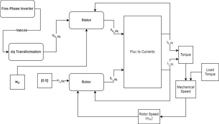
Stator and rotor resistance, leakage, magnetizing flux, and speed-coupling terms are assembled into dynamic voltage/flux equations.
Simulink Implementation
The mathematical model is implemented as a reusable simulation plant for control design, fault injection, and dataset generation.
03 / Evidence
Results & gallery
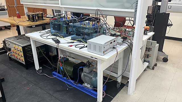
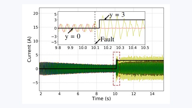
Project figures and laboratory photographs. Open a figure to inspect the detail; vector PDFs are available for the control diagrams.
Findings
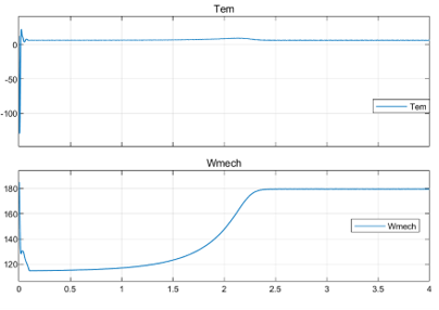
- The report develops phase-domain and reference-frame relationships and implements a Simulink model.
- It includes three-phase reference results and a five-phase investigation.
- The five-phase model is reported to work with sinusoidal excitation but to have convergence problems with filtered inverter excitation.
Scope & limitations
The early five-phase model converged with sinusoidal excitation but not with the filtered inverter output in the documented case. That limitation is distinct from the later drive-control implementation.