01 / Context
Overview
The converter is specified for 12 V nominal input and 24 V output at 20 kHz, with input voltage varied from 8–16 V and load resistance varied over a wide range. Switch-on and switch-off circuit equations were averaged and linearized to obtain a plant model suitable for feedback design.
A PI controller was tuned in MATLAB Control System Designer and then tested in Simulink across the requested input-voltage/load cases. The exercise therefore covers the complete chain from switching circuit equations to linearized model, controller tuning, and time-domain verification.
My work
- Derived switch-state equations and the averaged/linearized boost-converter model.
- Designed PI gains using MATLAB Control System Designer.
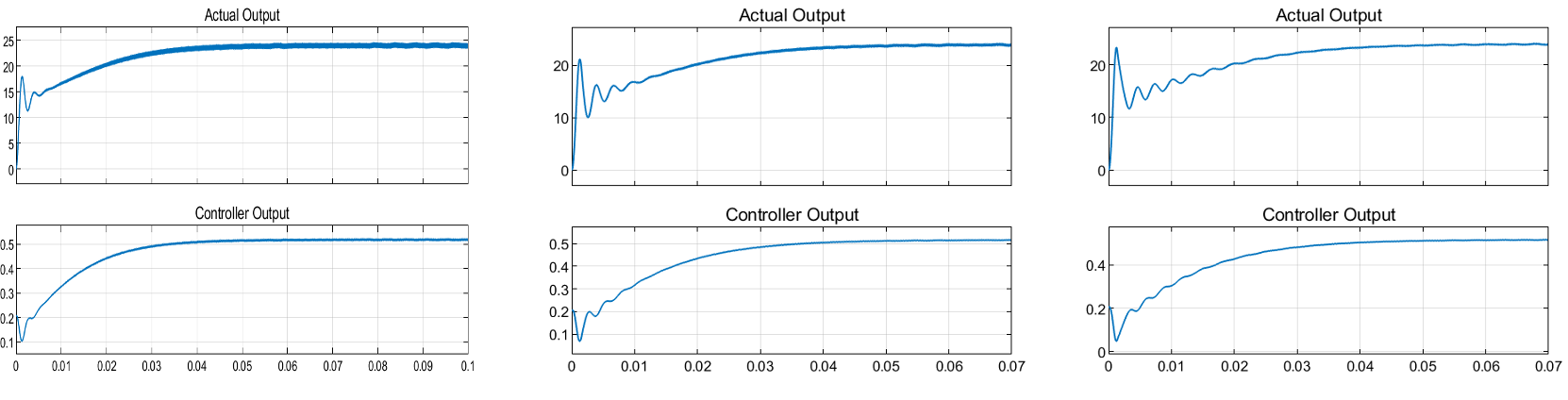
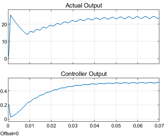
- Verified startup, settling, overshoot, ripple, and steady-state regulation under input/load variation.
02 / Approach
Methods & diagrams
State-Space Averaging
Switch-on and switch-off differential equations are combined around an operating point and linearized to obtain the small-signal plant.
PI Controller Design
The compensator is tuned against settling-time, overshoot, and output-voltage requirements.
Parametric Verification
The closed loop is simulated at multiple input voltages and resistive loads to identify performance limits.
03 / Evidence
Results & gallery
Project figures and laboratory photographs. Open a figure to inspect the detail; vector PDFs are available for the control diagrams.
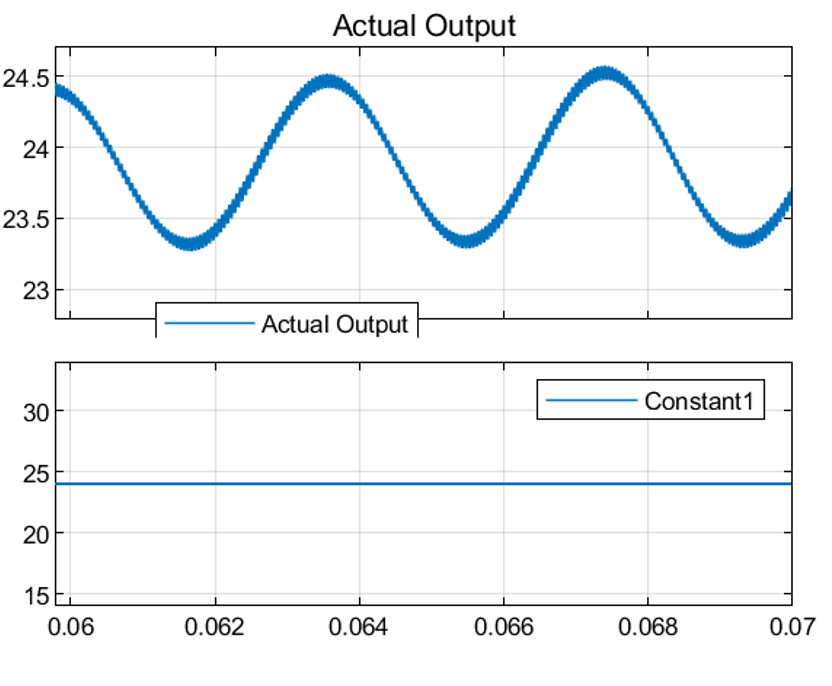
Findings
- The documented controller met the settling-time requirement across the tested cases.
- Overshoot/ripple requirements were not satisfied equally well at every extreme operating point, illustrating the limits of a single fixed PI design.
- The project connects small-signal modeling with controller tuning and off-nominal converter tests.
Scope & limitations
The PI tuning met the reported settling-time requirement, but ripple and overshoot limits were not met in every operating case. The nominal result should therefore be read alongside the off-nominal tests.